How to create a Maya set driven key in MotionBuilder
Hello, and welcome to this tutorial of how to create a Maya set driven key inside MotionBuilder using a relation constraint. This will go through the steps and explain a little about how its done. This tutorial is aimed at intermediate MotionBuilder users who are familiar with some basic constraining and what a set driven key in Maya is and knows how to look at one in the graph editor.
I wish MotionBuilder has a similar type of node that Maya has to create this type of connect, which it does, but it is a little harder to work with and I’ll explain why later.
What you will need:
- Maya (optional) – (Made in 2008, but saved as ASCII to change to another version)
- MotionBuilder (this tutorial was made using 7.5 Ext 2)
Download Tutorial Example Files – zip file
Step 1: Looking at the set driven key in Maya
You can follow along this tutorial by downloading the examples files above.
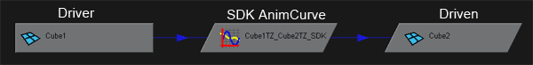
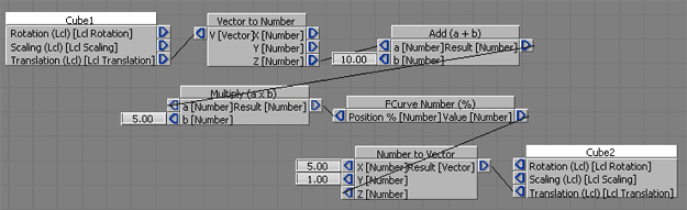
First, lets take a look at our simple SDK (set driven key) that we will recreate inside Maya. I am not going to explain how to create a SDK in Maya, I assume you know how to do this. But for this tutorial I am using two simple cubes, Cube1 and Cube2. Cube1’s translate Z is driving Cube2’s translate Z as shown below in the hypergraph:
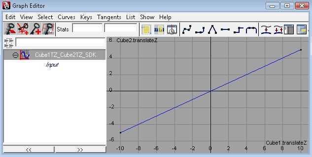
As you can see, when Cube1.translateZ is -10, Cube2.translateZ is -5. And Cube2 will end up at 5 when Cube1 moves to 10. A simple and straight forward set driven key animCurve. This is what we will create in MotionBuider which requires a little more work than you expect. You can see this file yourself in the example Maya file.
Step 2: Create our constraint and adding our driver and driven to it
Ok, now we are ready to crack open MotionBuilder and get started with the fun stuff. Since before I used simple cubes, I will just create new ones inside MotionBuilder through the asset browser. For more complex objects you will have to export that object from Maya and bring it into MB via fbx file format.
So with my two cubes created and and positioned the same as my Maya scene before I put the SDK on them (see the downloadable MB start file example)
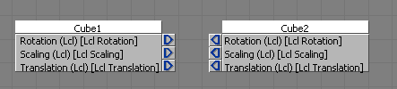
- Create a new relation constraint
- Now add Cube1 as my Sender
- And then add Cube2 as the Receiver
- Now on both the Sender AND Receiver right click over their boxes in the constraint and select Local Transformations (this will come more important if they had parents, so this is just for good habit)
So far so simple. Now we are ready to add the more complex parts and go into why we use them next.
Step 3: Adding the function boxes to the constraint
Here we get a little deeper into the setup and I will do my best to explain the reason behind everything. First let me explain the 3 main type of function boxes we will be using in this setup. They are Add (a + b), Multiply (a x b), and FCurve Number (%).

So let me explain,
The add and multiply I will explain why we use them after I explain if you are not familiar with the FCurve Number (%) function box. The FCurve Number (%) has, just like a SDK animCurve, 1 input that gives the position on the curve, or I could say the time. It will output the value at that given positon on the curve. But here’s the catch, the input only goes from 0 to 100 (this is where the % sign clues you in). What this means is that your first key, no matter where it is on the timeline, is at the 0% position and your last key is the 100% position. Ok, so uh, how do I convert my driver value keys to a percentage? Math, my friend. This where we use the other two functions, the add and multiply. Yes, you will actually have to think and possibly use a calculator when doing this.
First, lets tackle the problem of how we can make sure our first key which is at -10 (remember this is the driver value) is actually 0. Well we simply inverse that value and Add it to the driver before it gets to the FCurve. So, -10 + 10 = 0 . But luckily if the driver ever goes more negative, like -15, the input will be -5, which is ok as MB will still use the value of the first key (0%). Ok problem number 1 solved, next.
Ok, we now we have to convert our driver key values (-10 and 10) into a percentage so that when the driver value hits 10, it actually reaches the last key (100%). Well we know that -10 is 0% and 10 is 100%, so that means 50% is actually 0. So that means for every 1 frame we move, we go up 5% (10 x 5 = 50). Another way to calculate this is: 100 / (last key driver value – first key driver value) = 100 / (10 – -10) = 100 / (10 + 10) = 100 / 20 = 5. Told you it was a bit of math! Ok, so we must multiply the incoming value after we offset it with the Add function above by 5 to give us the proper position along the FCurve. With me so far? Good! If not, either read it again or just figure it out later.
Hopefully I explained the logic behind this and as you can see I wish MotionBuilder had a simplier FCurve type box like Maya has but we don’t so this is what we have to do. So now we can add and connect these boxes to our constraint.
- Under the Number group in the constraint, add a Add (a + b) and Multiply (a x b) function
- Now under the Other group, add a FCurve Number (%) box
- Connect the Add box output (Result) into the input of the Multiply’s A
- Then connect the output of the Multiply (Result) into the input of the FCurve Number (Position %)
Ok we are almost through, just a couple more steps and we are done.
Step 4: Connecting the driver and driven and setting values
So we almost have all our boxes setup, now we just have to connect the driver (Cube1) and our driven (Cube2) and set some values on the functions before we add our keys to the FCurve.
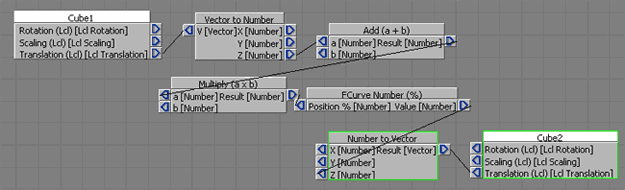
- Create a Vector to Number and a Number to Vector function under the Converters group in the constraint. This is so we can grab the one channel (X,Y,Z) to be the driver and plug the end result into the driven channel.
- Connect the Lcl Translation of Cube1 into the V (Vector) input of the Vector to Number box
- Now from the Vector to Number output Z, connect it to Add’s A input
- Connect the output vector, V of the Number to Vector into the Lcl Translation of Cube2
- Then connect the Value output of the FCurve Number (%) to the Z input on the Number to Vector box
You will notice in the 3D viewport Cube2 jumped back to center of the scene and is no longer Y=1 and X=5 like it was before. This is another problem I have with MotionBuilder. Even though there is no connections to the X and Y channels, it defaults to pass along the value of 0, rather than just leaving it alone. So we must add back our X and Y values:
- Right click over the plug <| channel on the Number to Vector and click Set Value
- Enter 5 in the box next to the X input
- Same thing for the Y by right clicking on the plug and setting the value to 1
Now our cube is back to where it originally was with the exception of Z. The FCurve function comes with default keys at 0 and 100 with values at 0 and 100. We will change these in a moment, but first lets set our add and multiply values.
- Same thing as above, right click on the b plug of the Add box and type in our offset we figured out before which is 10
- Now do the same thing on the b plug of the Multiply and set the value of our multiplier to give us our percentage which is 5
Ok we are ALMOST done. One last step!
Step 5: Inserting our keys on the FCurve Number (%)
Ok so all that is left is to copy the values on our Maya SDK curve and put it in the FCurve Number (%) box we have in MotionBuilder.
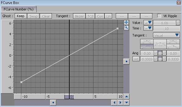
- Right click over FCurve Number (%) and click Edit which will open the FCurve box which allows you to see the keys and values of that curve.
- Click on the first key at 0 and change the time to -10 and then change the value to -5
- Now click on the last key at 100 and change the time to 10 and the value to 5
- Close the FCurve box
Look familar? Good! Because we are done! You can now move Cube1 along the translate Z and see it drive Cube2 like it did in Maya. You now created a SDK in MotionBuilder!
Now you could say, well you can save a step and just shift all the keys over so the first one starts at zero and not have to create offset Add function, and I would say you are correct, however when work with more complex key values and if you ever want to change the keys in Maya and update it in MotionBuilder, then you will have to figure out which key is where since they are now in a different spot in time. It is just easier to visualize and check your curves with the offset since you only have to change that number rather than shift all your keys without error.
I plan on releasing a package of scripts for both Maya and MotionBuilder that does all this work for you. So stay tuned for an update for these downloads.
Thank you for reading and following my tutorial. I hope it gave you some ideas on how to further see ways on how to replicate feature from Maya into MotionBuilder.